


What's all this about?
I can’t deny that I found Star Trek: Destination Europe 2016 in Birmingham, UK somewhat of a let down. Still, having managed to make what meagre fare there was last most of a day, I picked up a 2009 Movie Phaser on my way out. I’ve been on the fence for a while as to whether I wanted one or not and now that I’ve decided that I’d like to get one to add to my collection, the Playmates toys are going for stupid money on ebay and the full-on replica even more so. The Rubies one is a really cheap kids toy (which I still paid about 3 times what it’s worth for (£15 if you must know)) but the actual modelling on it is pretty good for a toy if you ignore the bizarre colours.

I imagine the board meeting at Rubies went something like this:
Director (puffs on cigar): ‘So the new Star Trek movie Phaser prop is chrome and silver. What have you boys got that’s close?’
Production manager:(pauses for dramatic effect) ‘Orange and white plastic!’
Director: ‘Perfect! Ship it!’
I’m not really sure what they were thinking with this other than maybe that a realistic looking Phaser might get the kid shot by the police?


Anyway, I thought a quick respray would see me to a fairly decent toy replica of the movie prop.
Getting Started
Once I got it home, I took a screwdriver to it and prayed that it wouldn’t require five pairs of hands and some specialist tools to reassemble again.
As luck would have it, the inside is very simple.

The trigger is a lever that you push down rather than in and that presses a clicker button on the tiny circuit board that in turn is wired to a tiny speaker. The sounds themselves are pretty crappy and alternate between tinny, sampled Phaser sound and weak, metallic fart noise. I think the latter is meant to be the emitter flip noise. Not sure.

The trigger is a lever that you push down rather than in and that presses a clicker button on the tiny circuit board that in turn is wired to a tiny speaker. The sounds themselves are pretty crappy and alternate between tinny, sampled Phaser sound and weak, metallic fart noise. I think the latter is meant to be the emitter flip noise. Not sure.
The emitter is a separate piece and could easily be turned if one of the lugs that secure it in place was circular and not arch-shaped. Not sure what the reason was for this. Maybe it was intended to turn but when a catch mechanism to stop it spinning freely was deemed too expensive, they just anchored it.
Making The Emitter Block Transparent
Now I wanted the emitters to be transparent red and blue (They aren’t, I know - more on this in a minute) so it occurred to me that, as the emitter block is a separate piece, I could cast it in clear resin and spray the emitters transparent red and blue. I had some RTV silicone mould-making rubber in the garage that was about three years out of date. I assumed it wouldn’t work but if it didn’t it was no biggie. I‘d just have to use the existing emitter and paint it non-transparent.
I glued the emitter halves together to make it ‘water’ tight so that silicone wouldn’t seep into it during casting and then sanded it down a bit to remove the join lines and just out of habit more than anything else.


Opening the tin I was expecting to find the RTV silicone completely cured but was pleasantly surprised to find it still very much in a liquid state. Equally the hardener was three years out of date and again, I expected it to not work. I gave it a go anyway. I created a moulding box by hot-glueing some foam board together. Lined it with modelling clay and set the emitter into it up to about half way.

I mixed up the silicone with the hardener and poured it. As luck would have it, I had exactly enough left to create a pretty solid mould around the emitter. I finished up and left it overnight.


I mixed up the silicone with the hardener and poured it. As luck would have it, I had exactly enough left to create a pretty solid mould around the emitter. I finished up and left it overnight.

Oh! That's not what I thought it was!
It was then that I decided to look at reference of the prop (I know. Shoot me). In doing so I learned several things:
- Firstly that the transparent red and blue emitters are on the Playmates toy. The movie prop stun emitter is chrome like the rest of the block (though the tip lights up blue in the movie) and the kill end is red but a metallic red as opposed to transparent.
- Secondly the movie prop has a rather nice curved kick out at the bottom of the grip as opposed to Rubies’ rather brutish rectangular block.
- The emitter nozzles are flush with the end of the cowling. The Rubies emitter is set too far forward.
- The prop has been somewhat redesigned and repainted for Star Trek Beyond and looks much cooler.
So I made some decisions.
- Firstly, I really like the idea of the transparent blue and red emitter nozzles and as I’d already poured the first part of the mould I decided I’d go with it.
- Secondly, I really wanted to add that kick at the bottom of the grip.
- Thirdly I’d reset the emitter block and make it so that it can turn - As previously mentioned, this requires only a little shaving of one of the lugs on the piece itself.
- Finally that I wanted it in Beyond colours but that presented a new problem. One of the coolest things about the Beyond redesign is the dark grey (black?) inlay on the grip. In order to do that I was going to have to score a division groove by hand which I knew before I even started would look like ass. I decided to cross that bridge once I got to it.
Back to the modelling
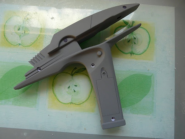
In the meantime I sanded off all the copyright and manufacturing info on the battery housing, masked off the circuit board and speaker holes to avoid clogging or damage from paint and sprayed the whole thing with grey primer. It looked immeasurably improved already.

Next morning I checked the mould and it was still gooey and sticky. I was a little disheartened as I assumed it wasn’t curing. The can did say allow 48 hours for full curing properties and as it had been left in the very cold garage overnight, it was hardly at room temperature. It’s been a few years since I last made silicone moulds so I couldn’t remember how long it used to take before becoming solid. I moved it indoors and put it in my wardrobe. By early evening it was pretty solid if still a little tacky meaning that it was definitely curing.
The Setting Dial
Something else I noticed on the movie prop was that it had a dial like the original 60’s prop. The Rubies toy had only two rectangular protuberances. They were set on a single, separate block, however allowing me to remove the piece. I then cut back one block and made an insert for it out of styrene. The block was three milimetres wide so I cut three pieces of 1 mil styrene and glued them together, leaving the centre piece longer so that I had a 1 mil tab I could slot and glue into the 1 mil opening on the piece. I rounded the styrene off and glued a strip of serrated styrene over the top. One setting dial. Perfect.


The Kick and the Lip
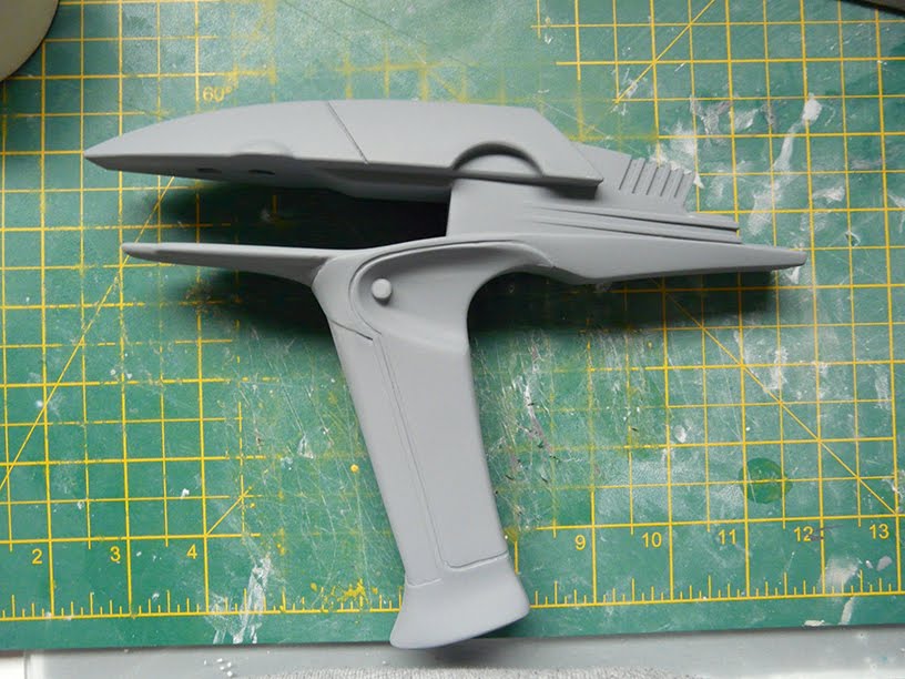
Next I moved on to the kick at the bottom of the grip. In Photoshop, I drew up a butplate, printed it out, glued it to some 1 mil styrene and cut it out.

I need the Phaser to be able to come apart at least until it’s finished so I cut it in half and glued each half to the bottom of the grip whilst it was assembled so that they match perfectly.


I need the Phaser to be able to come apart at least until it’s finished so I cut it in half and glued each half to the bottom of the grip whilst it was assembled so that they match perfectly.

At the same time, I started on the lip above the trigger. This is needed to separate the lower ‘jaw’ of the muzzle from the grip and was not present on the Rubies sculpt so I cut a thin strip of 1 mil styrene and glued it in place.

I masked off the bottom of the grip where I didn’t want filler - particularly I didn’t want it clogging the screw hole or overlapping the battery cover. Once that was done I took the Phaser apart (I don’t want the two halves sticking together) and worked in some P38 car body filler (I think it’s called Bondo in the US) to make the rough shape using the butplate and the styrene strip as a guide.

Once it had hardened, I sanded it back with some 60 grit sandpaper and then some 240. This required several passes with primer and finer sandpaper to finally work the ‘dinks’ out of and get it nice and smooth.

Once it had hardened, I sanded it back with some 60 grit sandpaper and then some 240. This required several passes with primer and finer sandpaper to finally work the ‘dinks’ out of and get it nice and smooth.
The join edges ended up being a little rounded which exaggerated the join at the base of the grip. I smeared some washing up liquid onto some styrene and applying P38 to the edge of each half, pressed it onto the styrene and let it cure - the liquid prevents it from sticking to the styrene. This, once sanded back gave it a nice crisp edge and a clean join.

The following day the silicone in the emitter block mould was solid so I took it out.

It had worked really well with the exception that it had stuck quite firmly to traces of the modelling clay. Fortunately I was able to remove most of it with a toothpick. Alarm bells were ringing though as it had not done that before. I made a new box to set the mould in, coated the emitter and the hardened silicone in liquid vaseline as a releasing agent, mixed up the remaining silicone and poured it, placing the mould back in the wardrobe.

Back to the Emitter
The following day the silicone in the emitter block mould was solid so I took it out.

It had worked really well with the exception that it had stuck quite firmly to traces of the modelling clay. Fortunately I was able to remove most of it with a toothpick. Alarm bells were ringing though as it had not done that before. I made a new box to set the mould in, coated the emitter and the hardened silicone in liquid vaseline as a releasing agent, mixed up the remaining silicone and poured it, placing the mould back in the wardrobe.
Oops!
Coincidentally, I was literally just thinking to myself, I’d better secure the speaker before all this assembling and disassembling and swinging about snap the speaker wires, when the speaker wires snapped. Both of them. I think I can re-solder them. I’m not sure. I’ll deal with that once the rest is done. It’d be nice to keep the crappy sounds but if I can’t it’s no big deal.
The Front and Butt Inlays (the easy ones)
Next on the Phaser was the inlay for the front of the grip. This was easy. I cut a narrow strip of .5 mil styrene and glued it in place. I then ran P38 along the outside edge at as shallow an angle as I could muster and sanded it back.


As I’d already decided that this was going to be a bastard hybrid of all versions of the movie prop and the Playmates toy and not a strictly accurate screen replica, I decided that it wouldn’t hurt to add a mod of my own. I really liked the idea of the serial number being inlaid on the but of the grip like the Star Trek V Assault Phaser.
I went back to Photoshop, opened the butplate that I’d drawn up and drew a smaller one inset. I also added a small rectangle.

Again, I pasted it to some 1 mil styrene, cut it out and glued it to the bottom of the grip. This allowed for a curved under-lip and a recessed rectangle in which I could place a printed label with a serial number that I’d also drawn up in Photoshop.


Again, I pasted it to some 1 mil styrene, cut it out and glued it to the bottom of the grip. This allowed for a curved under-lip and a recessed rectangle in which I could place a printed label with a serial number that I’d also drawn up in Photoshop.

I filled the gap between the edge of the serial plate and the butplate with P38 and sanded it back yet again.


Meanwhile back at the mould
Two days after pouring the second half of the mould, it had cured. It had up until the last minute, had a couple of tacky patches on top that seemed to be refusing to cure. It also felt soft and hollow in a line along the middle of the mould which worried me. It had eventually cured, however and I removed it from the box.
The first problem is that despite the liquid vaseline, it had largely cured to itself which I’ve never had before and I can only put it down to the fact that it was out of date. That meant a lot of tearing as I separated the halves. The mould itself, though, whilst not perfect was useable and solid.


I then looked up clear cast resin and discovered that it was available at a minimum in 1 kg cans. I only needed about 50 grammes. That coupled with the fact that it also has a 3 month shelf life meaning that I would almost certainly never use the rest of it for anything else, meant that it all felt like a lot of money and waste for something that was fundamentally wrong in the first place. So as the mould hadn’t really cost me anything I decided to bite the bullet and bin the idea and just paint the existing emitter block instead. I still have the mould though so I might go back to it one day.
The Accursed Rear Inlay
So next came the bit I was dreading, scoring the grip inlay.
I carefully drew the line I wanted in pencil and that went okay. I then cut very carefully along that line using a scalpel. That went okay. I then started scoring along the cut with a needle file and then a scribe. That didn’t go so well. Well, it was better than I expected. The straight lines were reasonably straight. It was just very scratchy and uneven and whilst it looked passable at a distance it didn’t bear close scrutiny. I could maybe have lived with it but I knew realistically that I probably would regret it if I left it.

I carefully drew the line I wanted in pencil and that went okay. I then cut very carefully along that line using a scalpel. That went okay. I then started scoring along the cut with a needle file and then a scribe. That didn’t go so well. Well, it was better than I expected. The straight lines were reasonably straight. It was just very scratchy and uneven and whilst it looked passable at a distance it didn’t bear close scrutiny. I could maybe have lived with it but I knew realistically that I probably would regret it if I left it.

I decided to use the same trick as I had for the inlay on the front of the grip. This would be trickier though as it not only had an unusual shape but also needed to fit perfectly with a companion piece and retain a uniform 1mm gap.
There was no way I could even contemplate eyeballing it. I decided that I needed to draw up a clean template in Photoshop. For that, though, I’d need to be able to draw on a decent photo of the gun and at exactly the right scale. I marked two points on the grip with pencil, measured the distance between them (102.5 mm) took a photo of the phaser grip as square on as I could and then brought it into Photoshop. Knowing the exact distance between the two points allowed me to scale the photo exactly and then I was able to draw on top of it using beziers to get nice clean, flowing lines. I used this to draw two lines either side leaving a 1 mm gap.


I printed the two mirrored shapes and pasted them onto .5 mil styrene and carefully cut them out. I say, ‘carefully’ but it was still pretty rough and uneven.


Once cut, I taped them to the grip on the Phaser and used them as a stencil to draw the line on to the grip in pencil. Once I was happy with the positioning of the pencil line, I used that as a guide to super-glue the pieces to the grip.


This proved to be a tad tricky on the battery compartment side as it went over the screw recess and along the bottom edge of the battery cover.
Once they were dry, I filled up the outside edge with P38 and sanded it nice and smooth.

This was then a long and tedious process of filling, sanding, priming, identifying errors, filling, sanding, priming, identifying errors, filling, sanding, priming, identifying errors, filling, sanding, priming, identifying errors, and so on and so on until I was happy to call it smooth and finished and tidy enough to walk away from.


This was then a long and tedious process of filling, sanding, priming, identifying errors, filling, sanding, priming, identifying errors, filling, sanding, priming, identifying errors, filling, sanding, priming, identifying errors, and so on and so on until I was happy to call it smooth and finished and tidy enough to walk away from.
In all honesty, I think the engraved approach was better. The styrene method has a more uniform line in straightness and thickness but it doesn’t have the subtlety or elegance of the engraved lines. I think what I really need to do is practice the engraving for future projects.
Painting the Emitter
Anyway, moving on. I was now ready to paint and the Emitter block came first.
I knew I wanted it to be silver/chrome and that I wanted to have the emitters be metallic blue and red. The original movie stun emitter is just chrome but I like the idea of the stun end being blue so I decided to paint the tip. I couldn’t find metallic red or blue in the store but they did have transparent red and blue so I bought those thinking I could spray them over the chrome for a metallic coloured finish.
I primed the emitter block in white as I thought that grey might dull it down too much. Then I sprayed the whole thing with several coats of Rustoleum brilliant finish chrome silver.
Once that had had a couple of days to dry I masked off the main body, broke out the airbrush and sprayed the stun emitter in transparent blue. This immediately beaded on the surface. Either I was too heavy handed or the Rustoleum was enamel which reacted with the acrylic blue or I'd thinned the blue paint too much (in retrospect, I actually think that this is more likely). Not sure, but I wiped it off, sanded back the Rustoleum and brush-painted acrylic chrome silver on to the exposed tips. I then did the blue and red again, built up in several light coats and the emitter was complete. Removing the masking tape brought some of the silver with it, but it was only light surface paint and didn’t damage the surface of the emitter itself. I can’t help feeling that the Rustoleum, whilst touch-dry needs some time to properly harden. I’ve no idea how long, as it’s already had about a week at time of writing.


Painting The Grip
Unfortunately I forgot to take pictures of this process so I'll just talk you through it and show the end results.
The colours I’ve chosen are not screen accurate but a sort of bastard hybrid of the 2009 version and the Beyond version and even then with the latter the colours are based on what I can tell from photos of the Anovos replica which looks like it’s being affected by the lighting anyway.
So I settled on mid grey for the grip, Dark grey for the grip inlay. Metallic gunmetal grey for the mid section and then chrome silver for the cowl. I originally intended to do the cowl the same mid grey as the grip as that’s how it looks in the Anovos pics. However, looking at some stills from the movie, it seems to be chrome. The same pic also makes the grip look like dark grey which means the grip inlay is probably black. Then again, that could be the lighting. Who knows? Before I went insane, I decided to just go with the version I had in my head which is the one described above as I really like the look of it even if it isn’t remotely accurate.
First, I mixed up some dark grey and some silver in a pot and sprayed the mid section. It came out a bit too light and silvery but I reserved final judgement until I could see it next to the other colours.
Once that was hardened, I masked it off using frog tape and sprayed the grip in the mid grey.
Once that was hardened, I masked it off using frog tape and sprayed the grip in the mid grey.
Once that was done, I masked off the mid-grey areas of the grip and sprayed the rear grip inlay, dark grey. I then unmasked the whole grip (leaving the mid section still masked) and sprayed the whole thing with several coats of Crystal Clear acrylic.
Next I masked off the grip, leaving only the cowl exposed and sprayed it with the Rustoleum chrome silver that I used for the emitter block. That, again turned out really well.
Unfortunately, when I removed all the masking, I decided that the mid section looked just a little too silvery and crappy.
Back to the bench. I masked off the entire grip except for the mid section and sprayed it dark grey and then crystal clear.
That looked a lot better but unfortunately when I removed the tape, as I feared from my experience with the emitter, it left feint blemishes on the lovely chrome finish on the cowl.
At this point, I honestly couldn’t face any more masking and spraying and decided that the blemishes were feint enough that I could live with them. There may come a day when I go back and respray the cowl, but this is not that day.
Finishing Up
At this point I re-soldered the wires for the speaker, attaching it once again to the circuit board. Miraculously it worked, leaving me feeling like some sort of electronics god!
I test-fitted the emitter too and it really was too tight, being set too far back. I should have shortened the block under the cowling when I had the chance but settled instead for simply dremelling out two new holes slightly forward of the first ones (but not as far forward as the original ones) and the emitter fit much better and turns quite easily too.
I assembled the whole gun, inserting the dial piece, emitter block and trigger and screwed it closed for (hopefully) the last time. The trigger worked. The sound worked and the emitter turns easily but has enough friction not to spin freely or waver about.
The final touch was the Starfleet serial number on the butt. I used Sticky-Backed Plastic (SBP) either side of the printed image. I could have used sticky tape but that tends to perish, yellow and flake off over time. I'm not aware that SBP does. I then cut it close to the edges of the printed image and trimmed it very slightly again after a test fit showed it to be fractionally too big.
Confident I wouldn't need to open the casing again, I used Araldite, a 2-part epoxy glue to stick it in place. I was worried that superglue or polystyrene cement might eat in to the SBP and soak in to the ink causing it to bleed or the SBP to bubble so Araldite seemed like a safe option.

Confident I wouldn't need to open the casing again, I used Araldite, a 2-part epoxy glue to stick it in place. I was worried that superglue or polystyrene cement might eat in to the SBP and soak in to the ink causing it to bleed or the SBP to bubble so Araldite seemed like a safe option.


No comments:
Post a Comment